How To Install Bar-end Turn Signals
by Craig Vechorik
Items required (Available from our online store):
insulated wire: 16 gauge (about 5 feet) or from our on line store, the following:
61 12 8 060 012--harness directional switch to bucket R26-R69S
61 12 8 060 013--harness inside handlebar for signals EFS&T
63 13 8 054 159--bar-end turn signals Hella original, quantity 2
Bulbs, quantity 2 of 6-volt or 12-volt:
07 11 9 978 302--light bulb Hella turn signal festoon bulb 6-volt
or
07 11 9 978 311--light bulb Hella turn signal festoon bulb 12v
Flasher (your choice of one type):
61 31 8 048 141--flasher signal indicator relay 6-volt
or
61 31 8 048 146--flasher signal indicator relay 12-volt
Directional switch:
BMW part number Hella® switch 61 31 8 048 183 &
base 32 72 2 072 180 --directional switch base sloping singles & twins 1955-1969 for throttles with the machined round flat spot or
32 72 1 230 878--adapter turn switch base with mounting screw for throttles without the machined round flat spot Earles Fork singles and twins 1955-1969
The switch
In order to add the switch (part # 61 31 8 048 183) and switch base
(part # 32 72 1 230 878) your throttle control must have a machined,
circular flat spot, with a threaded hole dead center of the circular
flat area. The original switch has terminal screws on the back which
are marked. The screw marked "H" is for the horn contact. This means when the directional switch is installed, you will be able to blow the horn by using the hi/low horn switch or the directional switch.
If your throttle is not of that design, you will have to use the adaper base, 32 72 1 230 878 and drill and tap a 5mm x .8 hole in your throttle to mount it. .
If you are mounting the signals on pre-existing handlebars with grips
and controls, you must determine if your handlebars have a exit hole
for the wires and locating "notches" on each end of the handlebar. The exit hole for the wires should be underneath the handlebar below the
center point. If the existing handlebars don't have this hole, you must
drill one. Mark the bars and then remove the bars from the motorcycle.
This is so that the hole is in the right position in relation to the
position you like your bars. If your bars do not have the hole, they also will not have the "notches" on the handle bar ends, and you will have to remove the grips and cut them. This is easily done, using a dremel tool with a cut off wheel. Cut two slots in the part, and the proper location, and snap the piece out, using a pair of needle nose vise grips.
Cut a circular hole in the end of each grip. An Exacto® hobby knife
works well. Notice that the Hella signals have a square locating peg on
one side of the stems. Also, notice that the yellow lenses of the
signals are offset, so the focus of the light will be directly forward
and directly back when mounted on the bike. You will want to
temporarily insert the signal into the open end of the bar and orient
the lenses in the proper position. The body of the signal should be
perpendicular to the ground.
Each end of the handlebar should have a locating notch in order to
properly fit the original Hella bar end signal. If it does not, mark
the bars as to where the slot needs to be cut. The square peg of the
signal should fit into the notch and still maintain the proper
orientation. Use a hack saw or a dremel tool with a cut off blade to cut a notch into each end of the
handlebar.
Setting up the signals
Pull one wire through each side of the handlebars and have both wires
exit through the center hole you drilled. One easy way to snake the
wire through the bars is to use a length of ball-type pull chain, such
as that used on lamp switches. Feed the chain through the bar to the
end. Tie the wire to the ball chain and pull the wire through. Be sure
and leave excess wire coming out of both ends and the center of the
bars.
Remove both lenses from the signals. Remove the slotted aluminum end
plug from the signals. Feed the wire through the center hole of each
signal. Shove the signals into place in the bars. Be sure that the
signals are shoved into the bar as deep as they will go. Sometimes it
helps to use a plastic dead blow hammer to gently drive the signals all
the way home into the bars.
In the signal, look through the hole from which you removed the
external plug. Notice that there is a slot, just to the side of the
hole that the wire emerges from, inside the signal. That is the
expansion screw that you must tighten with a screwdriver in order to
firmly mount the signal in the bars. Tighten that screw until the
signal is firmly held in place. Slip the bulb tension spring on the
wire and push it up the wire into the recess in the signal body. Strip
back a short portion of the insulation on the wire and tin the bare
wire with solder. Insert the soldered end of the wire into the brass
connector, (which is sheathed with a stepped nylon insulator) and
tighten the set screw onto the wire. Feed the excess wire back through
the stem of the signal, while simultaneously pulling the excess of the
wire out through the hole in the center of the bars. Repeat the whole
process on the other side of the bars.
Insert the festoon bulb into the signal. Make sure the pointed tip is
seated in the brass connector and the other tip is seated into the
center depression of the external aluminum plug, while carefully
threading the plug back into the body of the signal.
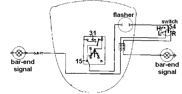
The Wiring
Connect a wire to the number 15 terminal on the
brown switch plate in the headlight bucket. Connect the other end to
the terminal marked "X" on the two prong flasher. The terminal marked "L" is then connected to the power in lead of the switch. You must use
a 6-volt or 12 volt, 18 watt flasher to match the load of the festoon bulbs. If
you do not, the lights will blink too fast, too slow, or not at all.
The part number for the correct 6 volt flasher is: 61 31 8 048 141. The part number for the correct 12 volt flasher is: 61 31 8 048 146. The next
wire must be connected to the "L" prong of the flasher and run to the
number 54 terminal of the directional switch. The directional switch
itself has three additional terminals. The "H" terminal stands for
"horn." You connect the other end of the wire to the "HO" terminal on the brown switch plate in the bucket so the horn will work from this switch.
The "L" means "left signal" and the "R" means "right signal."
The wire from the corresponding left and right directional bulbs
connect to these terminals. If you experience problems with the speed
of the flashing, or the lack of flashing, troubleshoot the system by
temporarily running a wire from the negative post of the battery to the
handlebar itself. Most of the time, a poor ground will cause the bulbs
not to blink. If you find this to be the case, you may have to run a
jumper wire from the handlebar riser to a solid ground on the engine or
into the headlight bucket. Terminal number 31 on the brown switch
board. The one with the brown wire is the ground terminal on the
headlight switch plate.
I take pride in selling quality parts for pre-1970 BMW motorcycles, and
for providing the best pre-1970 BMW motorcycle service available. If
you need more help in installing your bar-end signals, please call my
technical advice line. Please check our hours of operation. I'll be glad to try and help you trouble-shoot the problem.
FAQ:
Is there anyone repairing bar end turn signals when the expansion area cracks off?
Again, not to my knowledge. I have saved broken ones, by drilling a
small hole through the handlebar, and into the body of the bar end
signal, and then taping the hole and using a set screw to retain them.
It works. You must be sure the set screw does not protrude above the
surface of the bar.
How do you tell cheap signal copies from the authentic Hella brand signals?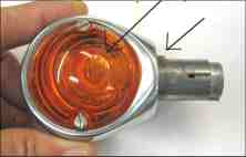
Real ones come in a bright yellow box with Hella logos printed in blue. Original signals have "Hella" cast in the yellow lens.
The fakes signals don't have a cast boss (raised square area) that fits
into a notch you must cut into the handle bar to fit it, keep it from
rotating.
Real Hella signals have a small terminal block inside with a set screw
to attach the wire to the terminal block. Fake signals have the wire
hard-soldered in and a short length of wire sticks out of the end of
the signal.
Regards,
Craig "Vech" Vechorik
Back to Tech Articles